WEBgui
QRcode connection
| IP client example http://xx.xx.xx.xx |
Hotspot example PUMPwlan123456 |
|
|---|---|---|
 |
 |
|
| connect to URI fluidicworks.com |
connect to SSID with pwd |
for a conveniant browser access, pls. open the QRcode application of your smartphone and scan the QRcode which is shown on the OLED display. The QRcode will be shown at startup automatically or it can be retrieved at any time by activating the IPshow function under the Services (SVC) Menu.
The pump can work in different access modes:
- regular IP client with Ethernet connection (DHCP service supplied by customers router)
- regular WLAN IP client (with correct WLAN configuration and DHCP service)
- as WLAN Hotspot (pump will act as WLAN router, clients can connect to hotspot pumpWLANxxxxxx)
- as WLAN Hotspot with working Ethernet connection
If pump is working as regular IP client, QRcode will connect to assigned IP-Address
If pump is working as Hotspot only, QRcode will connect to pumpWLANxxxxxx
Configuration options can be found in the Setup menu under WLAN and WLANhotspot tabs.
Start menu

To open the start page, pls. use one of the links below:
https://pump.local or
https://<ipaddress>
From this page, you can view documentation and start pumps WEBgui.
Pls. accept pumps self signed certificates.
Dashboard

The Dashboard (Dashb) gives the user access to mainly used functions and information for direct and fast usage.
P1 - P6: will show the SetPoint (SetP) and the actual pressure - process value (PV) for each licensed reservoir.
The pressure value can be set for each reservoir individually.
Orange colored reservoirs e.g. P1 indicate positive pressure reservoirs.
Blue colored reservoirs e.g. P3 indicate vacuum reservoirs.
All available macros can be selected from the macro pull down menu and started with the [Exec] button.
Different run modes like Operation [Oper], Standby [Stby], [AllOff] and injecting Solution[1-4] can also started from the Dashboard.
[Help] button will open a new browser tab with help information.
Menu button

By activating the menu button (☰), a navigation menu will appear.
By selecting a menu entry or by pushing the button again, the menu will disappear.
Slider menu

The Slider menu can directly reached from the Dashboard by pressing the [Slider] button. Each slider can control a set of reservoirs at once. With each [de-/sel] button a set of reservoirs can be composed for each slider. A reservoir set is indicated by magenta colored mbar units. Slider movements will control each pressure proportionally of each reservoir set.
Control menu
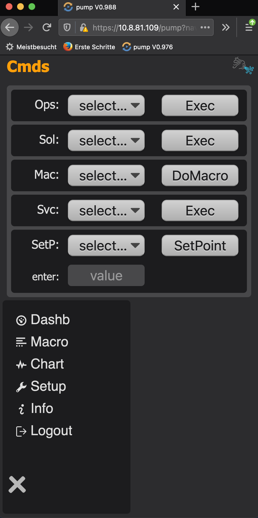
The Cntrl menu offer the usage of all functions on one page.
Activation by selection of desired function from pull down menu and start with [exec] button.
Chart menu

This page will give information about pump performance and leak rates of each reservoir.
The graphic is interactive in selecting the time range and average span.
Setup menu

In the Setup menu, you will find different sections (like HOME, PUMP …) to configure the device fitting your environmental needs.
[HOME] section:
Owner specific information (e.g. company name, dept.)
[PLATFORM] section:
Configuration of timezone, hostname, loglevels …
[PUMP] section:
Pump specific setup like enable/disable TCP server socket port …
[LICENSE] section:
enter license information
[SMTP] section:
enter mail server configuration
[WLAN] section:
for entering WLAN configuration data. Your pump will connect to your local WLAN.
[WLANhotspot] section:
The system can offer WLAN hotspot functionality.
Info menu

On this page you will find several technical and licensing information.
Macro menu

The macro menu shows up to 20 macro scripts, which are stored in the macro directory of your device. Macros can be exported and imported to/from an USB stick or via FTP protocol.
To create a new macro via the WEBgui, just type in a new filename and click the [Create] button.
Uploading a local filename.macro by a browser is possible by using [Choose file] and [Upload] buttons.
Opening a specific macro for inspection or editing, just click the [macroname] tab.
Save your script by using [update].
Browser support
| Chrome | Edge | IE | Firefox | Safari | Opera |
|---|---|---|---|---|---|
| YES | ok | no | YES | ok | ok |
Command reference
[Format]
<command> <param1>[,<param2>,...]
<command> (<param1>[,<param2>,...])
Example:
setP 1,220      # format #1: recommended format
setP (1,220)    # format #2: pls. do not use
Due to compatibility reasons, parameter can be surrounded by rounded brackets ( )
Recommended format: without rounded brackets, shown in format #1.
[Parameter]
Parameters are separated by , (comma).
Commands are NOT case sensitive.
Labels are case sensitive.
Parameter types:
<register>: -1,0,1,...9
            e.g. REG-1,REG9

<integer>:  -1,0,1,2,3 ...

<float>:    -1.234,3.1415 ...

<number>:   <integer>, <float>
            e.g. -1,1.234 ...

<label>:    Alphanumeric (ASCII Characters [0x20..0x7e], [space..~])
            e.g. Label1

<text>:     Alphanumeric (ASCII Characters [0x20..0x7e], [space..~])
            text can be unicode encoded e.g. H\u2082O temp 25\u00b0C

<setstrng>: 0,x,1
            0:ON; 1:OFF;
            x:unaffected

errorlevel in REG-1:
every macro command will set an errorlevel
 0: command execution was successful
-1: command execution was not successful

positive levels and zero (>=0) can be
interpreted as successful command execution.

negative levels (<0) can be interpreted
as unsuccessful command execution.Controlling the macro command sequence by errorlevel, using JS and JNS is recommended.
Example:
# Begin of Macro
DoMacro SetMyDefaults
MOV 1,5
Label Loop
SerWrite /dev/ttyUSB0 go next
JS -1,HndlErrRead
#
# Do some microfluidic stuff
#
DEC 1
JNZ 1,Loop
JMP EndMacro
Label HndlErrRead
TEXT Error\nReading device
Label EndMacro
# End of Macro
analog/digital IO
AOut
Set Analog (DAC) Output
An optional module is required.
AOut <channel>,<vrange%>
Parameter:
DAC channel:    1 - 4

vrange%:        0 - 1.0 (0V - 5V)
Example:
AOut 2,0.50     # Set DAC2 Output to 50% of
                # available voltage range (-> 2.5V)
DOut
Set Digital Output
DOut <port>,<level>
Parameter:
Port:           1 - 4

Level:          0 or 1
Example:
DOut 2,1 # Set Port 2 to highDOutM
Set available Dout ports On/Off at once
DOutM <setstring>
Parameter:
Ports:          1 - 4

0:              OFF
1:              ON
x:              unaffected
Example:
DOutM 0,x,1,0will set port #1,4 OFF; let port#2 unaffected; set port#3 ON
Play
Play a file (.mp3 .wav) on audio output (3.5mm jack).
file resides in macro directory.
An optional module is required.
Play <file>
Example:
play testfile.mp3SetRelais
Set available Relais On/Off.
An optional module is required.
setRelais <setstring>
Parameter:
Relais:     1 - 3
Relais 3:   switches HighVoltage ON / OFF

0:          ON
1:          OFF
x:          unaffected
Example:
setRelais 0,x,1     # set Relais#1 OFF
                    # let Relais#2 unaffected
                    # set HighVoltage ON
SyncOut
Generate a trigger pulse on available Output.
syncOut [<outpin>,]<pulselength>
Parameter:
TriggerOut:         1 - 2

PulseLength:        1 - 100 msec
Example:
syncOut 2,50        # 50msec pulse on trigger out #2
syncOut 75          # 75msec pulse on trigger out #1
WaitSync
Wait for a trigger pulse on available Input.
waitSync <inputpin>,<waveform>[,<timeout>]
Parameter:
TriggerIn:      1 - 2

WaveForm:       RISE or FALL

Timeout:        >=0 seconds
Example:
waitSync 2,RISE     # wait on rising  pulse on trigger in #2
waitSync 1,FALL,60  # wait on falling pulse on trigger in #1,
                    # timeout 60 seconds
X10
Set X10 general purpose (GPIO) output.
X10 <ON|OFF>
Parameter:
ON or OFF: (default: OFF)Example:
X10 ON      # set GPIO output HIGH,
            # if configured as OUTPUT
X10 ON      # enable frequency on GPIO output,
            # if configured as frequency OUTPUT
X10 OFF     # set GPIO output LOW,
            # if configured as OUTPUT,
            # or disable frequency
X10mode
Set mode of X10 general purpose (GPIO) output
X10mode <OUTPUT|frequency_Hz>
Parameter:
OUTPUT:             configure as output (default: OUTPUT)
<frequency_Hz>:     4690 - 19200000     (4690Hz - 19.2MHz)
Example (sequence 1):
X10mode OUTPUT      # set GPIO to output
X10 ON              # set output level HIGH
sleep 10            # wait 10 secs
X10 OFF             # set output level LOW
Example (sequence 2):
X10mode 5500        # set output frequency to 5500Hz
X10 ON              # switch frequency on,
                    # set in previous command
sleep 10            # wait 10 secs
X10 OFF             # switch frequency off
Backup/Restore
files are stored in directory ~/bck
filename will contain backup type, device serial number and timestamp.
filename format:

bck<type>_<snr>_<timestamp>.tgz

type:
cfg         configuration backup data
exe         application backup

timestamp:  YYYYMMDDhhmmss  (e.g. 20181006234505)
CreaCfgFil
create backup file (bckcfg_<snr>_<timestamp>.tgz) of configuration data.
CreaCfgFil
RstCfgFil
restore latest config file which was created with CreaCfgFil
RstCfgFil
Support File
files are stored in directory ~/maint
filename will contain devices serial number and ssl identification.
file ist encrypted by ssl certificate.
filename format:

supportfile_<snr>.tgz.<sslID>.ssl

sslID:      <hexstring> (e.g. 3a...e5)
CreaSupFil
create support file which contains log data.
The file can be uploaded with UplSupFil
CreaSupFil
UplSupFil
upload ssl encrypted support file with was created by CreaSupFil
UplSupFil
DC/Stepper Motor
DCMfreq
DC motor frequency in Hz
DCMfreq <freq_Hz>
Parameter:
freq_Hz: 10 - 2000 (default: 1000)Example:
DCMfreq 1000 # motor freq 1000HzDCMpwm
DC motor PWM dutycycle
DCMpwm <dutycycle%>
Parameter:
dutycycle%: 0 - 1.0 (default: 0)Example:
DCMpwm 0        # motor is OFF
DCMpwm 0.5      # motor dutycycle 50%.
                # Turns with half speed
DCMpwm 1        # motor is ON.
                # Turns in full speed
STPdir
Stepper motor set direction
STPdir <LEFT|RIGHT>
Example:
STPdir LEFT     # motor should turn left
STPdir RIGHT    # motor should turn right (default)
STPenable
Enable/Disable stepper motor
STPenable <0|1>
Example:
STPenable 0     # motor will stop  movement (default)
STPenable 1     # motor will start movement
STPmode
Set step mode
STPmode <stepmode>
Parameter:
stepmode:   0 - 4

0:          full step
1:          half step
2:          1/4 step  (default)
3:          1/8 step
4:          1/16 step
Example:
STPmode 3   # set motor to 1/8 step
STPmode 0   # full step
STPrev
Set stepper motor revolution (steps per turn in full step)
STPrev <stepsperturn>
Parameter:
stepsperturn: 10 - 40000 (default: 200)Example:
STPrev 200      # resolution is 1.8 degree per step
                # 200 steps per turn
STPsleep
Set stepper motor to sleep/ready modus
STPsleep <number>
Example:
STPsleep 0      # motor will be set to sleep mode
STPsleep 1      # motor will be set to active mode
                # (activate charge pump, takes some msec)
STPspeed
Stepper motor speed in Hz
STPspeed <speed_Hz>
Parameter:
speed_Hz: 10 - 800 (default: 400)Example:
STPspeed 400    # motor speed 400Hz
STPspeed 100    # motor speed 100Hz
STPrun
Set run time in seconds (sec)
STPrun <runtim_sec>,<timeout_sec>
Parameter:
runtim_sec:

    >0: motor will turn <runtime_sec> seconds

     0: motor will turn continuously

    -1: motor will turn until switch#1
        position reached.

    -2: motor will turn until switch#2
        position reached.

    -3: motor will turn until switch#1
        or switch#2 pos. reached
Example:
STPrun 2.5      # motor turns 2.5 secs
STPrun 0        # motor turns continuously
STPrun -3,1.0   # motor turns until switch#1 or #2
                # position reached or timeout of 1sec
STPturn
Set amount of rotations/turns
STPturn <rotations>
Example:
STPturn 0.75 # 3/4 turnExample (macro):
mov 1,5             # 5x loop
LABEL LAB1
sleep 1
STPDir LEFT         # motor direction Left
STPspeed 800        # set speed to 800Hz (fast)
STPTurn 5           # do 5 turns
STPspeed 400        # set speed to 400Hz
STPTurn 0.75        # do a 3/4 turn
STPspeed 50         # speed 50Hz (slow)
STPTurn 0.20        # 1/5 turn
STPspeed 10         # very slow
STPTurn 0.05
STPDir RIGHT        # do same action to the right
STPTurn 0.05
STPspeed 50
STPTurn 0.20
STPspeed 400
STPTurn 0.75
STPspeed 800
STPTurn 5
sleep 2             # wait 2 secs
dec 1
jnz 1,LAB1          # Jump to label LAB1 5 times
text FINISH         # show FINISH on OLED display
SERVO
Turn servo to defined angle, or enable/disable DB9 pin for servo mode
SERVO <num>,<disable|enable>[,<profile>]
SERVO <num>,<angle>[,sync]
Parameter for setup:
disable: set DB9 X1 pin to (STP/DCM) motor mode (default)
enable:  set DB9 X1 pin to servo mode
servo profile parameter (predefined):
DFLT:       # 50,180,-90,90, 800,2200
SG90:       # 50,100,-90,90, 600,2600
MG90S:      # 50,100,-90,90,1000,2000
MG996R:     # 50,170,-60,60,1000,2000
servo profile parameter (by user definition):
USR,<freq>,<waittime>,<ANGmin>,<ANGmax>,<DTYmin>,<DTYmax>

USR:        indicator for user defined profile
freq:       PWM frequency in Hz                      (e.g.   50)
waittime:   time in ms, servo needs for 60 degree    (e.g.  180)
ANGmin:     minimum angle, left  position in degree  (e.g.  -90)
ANGmax:     maximum angle, right position in degree  (e.g.   90)
DTYmin:     duty cycle for minimum angle in microsec (e.g.  800)
DTYmax:     duty cycle for maximum angle in microsec (e.g. 2200)
Parameter for operation:
num:     1 - 2      # use Servo pin #1 or #2
angle:   -90 ... 90 # integer position -90:left 0:middle 90:right
sync:    1          # sync on, until servo has reached new position
Example:
SERVO 2,enable,SG90 # set DB9 X1 pin to servo2 mode with SG90 profile
SERVO 1,enable,USR,50,180,-90,90,800,2200   # user defined profile
                    # enable/disable is needed only once per servo
SERVO 2,-45,1       # turn Servo#2 to -45 degree, wait until finished
Firewall
pump uses firewalld (FWD) to implement network security.
Configuration changes executed through Setup menu e.g. opening/closing ports for SCPI, MQTT or WebSRV access, limiting access via allow lists, will need reconfiguration of firewalld rules. If the pump detects that changes to the ruleset become necessary, it will notify the user with a corresponding message on the Dashboard and urges to execute the FWD apply command.
FWD apply
Apply configuration changes and configure firewalld rules.
FWD apply
This command will trigger a whole bunch of commands to configure firewalld’s ruleset. The execution takes place in the background and requires about 20 seconds. The ruleset of all active zones can be evaluated on Info menu under the [firewall (active rules)] tab.
public (active)
  target: default
  icmp-block-inversion: no
  interfaces: eth0 wlan0
  sources:
  services: dhcpv6-client ftp http https mdns ssh upnp-client
  ports:
  protocols:
  forward: no
  masquerade: yes
  forward-ports:
  source-ports:
  icmp-blocks:
  rich rules:
    rule source mac="8C:85:90:12:34:56" port port="5025" protocol="tcp" accept
    rule family="ipv4" source address="10.8.81.100" port port="5025" protocol="tcp" accept
trusted (active)
  target: ACCEPT
  icmp-block-inversion: no
  interfaces: ap0
  sources: 10.3.141.0/24
  services:
  ports:
  protocols:
  forward: no
  masquerade: no
  forward-ports:
  source-ports:
  icmp-blocks:
  rich rules:
This ruleset will show, that network client access on ethernet (eth0) and wireless lan (wlan0) is allowed for the following protocols:
public zone:
- DHCP: assign IP6 address to pump on request. rule for IP4 not needed, already enabled
- ftp: FTP server process is running on pump, this rule will give clients access
- http: clients can access WEBgui through webserver standard port 80
- https: clients can access WEBgui through webserver standard port 443
- mdns: Avahi/Bonjour protocol. mac/linux clients can discover pump more conveniant
- ssh: will give administrators remote access
- upnp: plug and play protocol, conveniant network client access
- 5025: SCPI port, e.g. for LABview integration and remote control for two specific clients only, which are defined by IP address 10.8.81.100 and a device with mac address 8C:85:90:12:34:56. Limiting access for specific clients can be achieved by maintaining the SCPI Allow comma-separated (csv) list (e.g. 10.8.81.100,8C:85:90:12:34:56)
Clients connected on Hotspot wlan service (interface ap0) will be treated as trusted.
trusted zone:
all clients with an IP address within the 10.3.141.0/24 subnet have unlimited access.
Macro Control
<register>
The system offers 10 registers numbered [0..9] which are read and writeable by several macro commands (e.g. mov, dec, inc, jnz …). They act globally and can be used to pass results to/from a called macro to the calling macro (pls. see DoMacro command).
<errorlevel>
The numbered register -1 represents the errorlevel of a preceding macro command. This register is read only.
ask
Will ask for user response. A question will be displayed on the OLED. The response can be given by the encoder wheel.
ask[<askType>,<TimeOut>,<TimeOutDefault>,[<TargetRegister>,]]<Question>
Parameter:
askType:            <YesNo,Integer,float1,float2>

Question:           that will be displayed on the OLED

TimeOut:            If an answer is not given within the
                    <timeout> seconds (default 60),
TimeOutDefault:     will be used.

TargetRegister:     Answer will be stored in an
                    internal counter register.


Shortcuts for Question:
ask_to_continue     AskType:            YesNo
                    TimeOut:            60
                    TimeOutDefault:     0
                    Question:           Continue?\n(Yes/No)

ask_for_passes      AskType:            Integer
                    TimeOut:            60
                    TimeOutDefault:     0
                    Question:           Passes?
Example:
ask ask_to_continue                 # Will ask for Yes or No.
ask YesNo,60,0,Continue?\n(Yes/No)  # same as above
                                    # TimeOut 60sec
                                    # Default answer 0 (No),
                                    # a jump to the end of
                                    # the macro will be
                                    # executed.

ask YesNo,30,1,Continue?\n(Yes/No)  # If answer is not given
                                    # within 30 secondes,
                                    # 1 (Yes) will be given.

ask ask_for_passes                  # Will ask for a number
                                    # and stores the result
                                    # into Register0.
                                    # TimeOut 60 sec

ask Integer,20,5,0,Passes?          # Will ask for a count
                                    # and stores the result
                                    # into Register0.
                                    # If answer is not
                                    # given within 20 sec.

                                    # A count of 5 will be
                                    # stored into Register0.

                                    # Remark: \n
                                    # insert Linefeed (LF)
DoMacro
Call a Macro within a Macro. Acts like calling a subprogram. The intention is, to define common information in a central place, which can be used by any other macro.
Macros have the file extension .macro and are stored in directory ~/macro
DoMacro <macroname>
Example:
Macro MyMacro1:
beep 5
# set some defaults, pon poff ...
DoMacro SetMyDefaults
oper
sleep 1
# do some stuff ...
Macro SetMyDefaults:
SetPON  220
SetPOFF 24
alias   LabTable,/dev/ttyUSB2
setTTY  LabTable@115200 -cstopb -parenb
cmp
Compare register content with a value.
Compare register-content1 with register-content2.
cmp <register>,<value>
cmp <register1>,<register2>
Example 1:
mov REG1,3      # fill register1 with value 3
cmp REG1,5      # compare content of register1
                # (value=3) with value 5
                # errorlevel: -2 (3-5)
Example 2:
mov REG4,3      # fill register4 with value 3
mov REG7,5      # fill register7 with value 5
cmp REG4,REG7   # compare content of reg4 (3) with reg7 (5)
js  REG-1,LAB   # will jump (jmp on sign) to LAB
                # errorlevel: -2 (3-5)
                # (because result is negative)
dec
Decrement register content by a value.
dec <register>[,<value>]
Example:
dec REG1        # decrement register 1 by 1
dec REG1,2      # decrement register 1 by 2
inc
Increment register content by a value.
inc <register>[,<value>]
Example:
inc REG1        # increment register 1 by 1
inc REG1,2      # increment register 1 by 2
jmp
Jump (unconditional).
jmp <label>
Example:
jmp Loop1 # jump to Label Loop1jnz
Jump if register content is non zero.
jnz <register>,<label>
Example:
jnz REG1,Loop1  # jump to Label Loop1,
                # if register 1 content is not 0
jz
Jump if register content is zero.
jz <register>,<label>
Example:
jz REG1,Loop1   # jump to Label Loop1,
                # if register 1 content is 0
js
Jump if register content is negative (jumpOnSign).
js <register>,<label>
Example:
js REG1,Loop1   # jump to Label Loop1,
                # if register 1 content is <0
jns
Jump if register content is positive (jumpOnNOTSign).
jns <register>,<label>
Example:
jns REG1,Loop1  # jump to Label Loop1,
                # if register 1 content is >=0
Example (macro with control structures) :
# remark
ask Integer,20,5,0,Passes?  { multiline comment:
                              store answer in register0.
                              TimeOut is 20 secs.
                              Default value 5 }
Label Loop1                 # jump label
#
# do something else
# ...
dec REG0,1                  # decrement register 0 by 1
jnz REG0,Loop1              # jump to Loop1,
                            # if register 0 <>0
pumpsOff                    # continue here,
                            # if register 0 = 0
text DONE!!!                # show DONE!!! on OLED Display
label
Places a jump target within a macro.
labelstring is case sensitive.
label <labelstring>
Example:
label Loop1sleep
command sequence will sleep for <number> seconds.
sleep <number>
Example:
sleep 5         # sleep for 5 secs
sleep 1.2       # sleep for 1200 millisecs
mov
Move a numerical value to a register.
Move a value from register source to register target.
mov <regtarget>,<number>
mov <regtarget>,<regsource>
Example:
mov 3,5         # move value 5 into register 3
mov REG3,5      # move value 5 into register 3
mov REG1,REG3   # move content of register 3 (5)
                # to register 1
testmode
Command sequence will be set to testmode. All pressure manipulating commands will not be executed (e.g. AllOff). Only flow control commands like JNZ, DEC, INC and sleep commands will be executed. The intention of this command is to analyze and observing the behavior of a Macro for testing purposes. Testmode will be inherited from the calling macro to all subsequent called macros.
testmode
Example:
TestMode()
setVswitch(-200)    # will not be executed
sleep(5)
setVswitch(-10)     # will not be executed
sleep(2)
solution1()         # will not be executed
sleep(5)
solution3()         # will not be executed
sleep(10)
allOff()            # will not be executed
ask(Continue?\n(Yes/No))
solution2()         # will not be executed
sleep(10)
allOff()            # will not be executed
pumpsOff()          # will not be executed
text(DONE!!!)
msg
A message will be displayed in the web gui.
msg [<level>,]"<text>"
Parameter:
| level | text color | error level |
|---|---|---|
| ERR | red | ERROR |
| WRN | yellow | WARNING |
| SUC | green | SUCCESS |
| INF | white | INFO (default) |
| URG | red | URGENT |
| MAG | magenta | |
| RED | red | |
| ORA | orange | |
| YLW | yellow | |
| GRN | green | |
| LGR | light green | |
| BLU | blue | |
| BLK | black | |
| WHT | white |
Example:
msg "a Text"                  # display 'a Text' in web gui
msg blu,"Line1\nLine2"        # display use 2 lines, color blue
msg mag,"info ""text"""       # display 'info "text"' in magenta
msg "H\u2082O temp 25\u00b0C" # display H2O temp 25C (unicode)
last example will display: H2O temp 25°C
text
A message will be displayed on the OLED.
text[<DisplayTimeInSecs>,]<text>
Example:
text aText              # display 'aText' on OLED for
                        # 5 sec (default)
text 10,Line1\nLine2    # display 10 sec 'Line1' on first
                        # line and 'Line2' on 2. Line
waitTime
Wait until given time has reached.
waitTime <XMLDateTimeStamp>
Example:
waitTime 2018-07-10T14:28:15+02:00  # UTC: 12:28:15 10-Jul-2018
waitTime 2018-07-10T14:28:15-08:00  # UTC: 06:28:15 10-Jul-2018
waitTime 14:28:15+02:00             # UTC: 12:28:15 today
waitTime 14:28:15Z                  # UTC: 14:28:15 today
waitTime 14:28:15                   # local time: 14:28:15 today
Requirement:
- TimeZone must be set accordingly
- NTP protocol will be used to adjust internal clock
- internet or RTC required for proper operation
further information about XML TimeStamps:
http://books.xmlschemata.org/relaxng/ch19-77049.html
Pressure Control
AllOff
Pump will be set to Off Mode.
AllOff
Clean
Pump will be set to cleaning Mode.
clean [<integer>]
Parameter:
<integer> determines the amount of seconds

Maximum time:       10 seconds

default value:       2 seconds
Example:
clean               # cleaning time 2 secs
clean 8             # cleaning time 8 secs
Init
Pump will be set to Initialize Mode.
init
Oper
Pump will be set to Operation Mode.
oper
SetMeassure
Set channel to meassure mode.
In this mode, the channel will meassure external connected pressure or vacuum.
Leave this mode with SetPoint (setP) function.
setMeassure <reservoir>
Parameter:
Reservoir: 1 - 8Example:
setMeassure 3 # Set reservoir 3 to meassure modeSetP
Set pressure/vacuum value (SetPoint) for available reservoir.
setP <reservoir>,<number>[,oper,stby,temp]
Parameter:
Reservoir:          1 - 8

Pressure SetPoint:  0 ... +500  (mbar)

Vacuum SetPoint:    -300 ... 0  (mbar)

Profile:            oper, stby, temp (default: oper)
oper and stby will affect according profile.
temp will not affect any profile and is a temporary SetPoint.
Example:
setP 1,220          # SetPoint 220mbar for reservoir 1
setPON 220          # SetPoint 220mbar for reservoir 1
setP 3,-110         # Vacuum SetPoint -110mbar for reservoir 3
setVSwitch -110     # Vacuum SetPoint -110mbar for reservoir 4&5
Reservoir pressure default values (mbar):
| Res | setAlias | Type | min | stby | oper | init | clean | max |
|---|---|---|---|---|---|---|---|---|
| #1 | setPON | 0 | 10 | 220 | 220 | 300 | 500 | |
| #2 | setPOFF | 0 | 10 | 20 | 500 | |||
| #3 | setVRecirc | Vacuum | -300 | -45 | -115 | 0 | ||
| #4 | setVRecirc2 | Vacuum | -300 | -10 | -115 | 0 | ||
| #5 | setVRecirc1 | Vacuum | -300 | -10 | -115 | 0 | ||
| #6 | setP6 | 0 | 110 | 500 | ||||
| #7 | setP7 | 0 | 110 | 500 | ||||
| #8 | setP8 | Vacuum | -300 | -115 | 0 | |||
| #4&5 | setVSwitch | Vacuum | -300 | -10 | -115 | 0 |
SetSTBY
Set Standby pressure/vacuum value for available reservoir.
setSTBY <reservoir>,<number>
Parameter:
Reservoir:          1 - 8

Pressure Standby:   0 ... +500  (mbar)

Vacuum Standby:     -300 ... 0  (mbar)
Example:
setSTBY 3,-45   # Standby pressure -45mbar
                # for vacuum reservoir 3
SolGroup
Accumulate operation on Manifold valves.
solGroup [0|1]
Parameter:
0 (OFF):
Selecting a specific solution, closes all other valves first
and open/close selected valve.
A transition from ON to OFF, all valves will be closed.

1 (ON):
Selecting a specific solution will open/close valve and
let other valves unchanged.
Indicated on OLED display with 'c'-flag.

not given:
Toggle: ON->OFF; OFF->ON
Solution
switch solution<nr> OFF, ON or pulselength
solution <solnr>[,0|1][,<pulselength>]
solution<solnr> [0|1][,<pulselength>]
Parameter:
<solnr>:    1 - 6

0:          OFF

1:          ON (default)

not given:  Toggle: ON->OFF; OFF->ON

pulselength:pulse in seconds (max. 2.0 seconds)
Example:
solution1           # on channel 1, switch solution ON
solution 1          # on channel 1, switch solution OFF

solution1  0        # on channel 1, switch solution OFF
solution 1,1,0.3    # on channel 1, switch solution ON for 0.3 seconds
solution1           # on channel 1, toggle solution OFF
                    # (state before: ON)
solution1           # on channel 1, toggle solution ON
                    # (state before: OFF)
StBy
Pump will be set to Standby Mode.
stby
WaveSet
Define a wave for SetPoints.
Waveforms (mode):
| Linear | Triangle | SawTooth | Square | Sinusoidal | S-shape |
|---|---|---|---|---|---|
 |
 |
 |
 |
 |
 |
| 0 | 1 | 2 | 3 | 4 | 5 |
WaveSet <reservoir>,<ivs>,<mode>,<cnt>,<startp>,<endp>[,dtyc]
Parameter:
reservoir:      1 - 8

ivs:            Interval in seconds. Time between loading
                next SetPoint.

cnt:            count of intermediate SetPoint values
                between <startp> and <endp>

startp:         SetPoint start value.

endp:           SetPoint end value.

dtyc:           0 - 1, duty cycle for square wave form
                (optional).
                e.g.: 0.75 -> 25% <startp>, 75% <endp>

mode:           0 - 5

0: linear       SetPoint smooth increase from <startp> to
                <endp> and remain.

1: triangle     smooth oscillate between <startp> and <endp>

2: sawtooth     smooth increase from <startp> to <endp>,
                Falldown to <startp>

3: square       Alternate between <startp> and <endp>,
                influenced by <dtyc>

4: sinusoidal   oscillation between <startp> and <endp>

5: S-shape      oscillation between <startp> and <endp>
WaveSet <reservoir>,<ivs>,<fmode>,<filnam.wave>
Parameter:
filnam:         load user specific wave form

fmode:          determine idx movement within the wave.
                  0 ->  after reaching last idx,
                        remain at last idx
                  1 ->  after reaching last idx,
                        decrement idx by 1 until idx=0
                  2 ->  after reaching last idx,
                        start at idx 0

filelocation:   in ~/macro directory.
                FileExtension is '.wave'

fileformat:     one SetPoint value <number> per line.
                e.g: 30.0 ... 105.0
Wave
Enable/Disable Wave operation.
Wave <reservoir>,<0|1>[,startidx]
Parameter:
reservoir:      1 - 8

0:              disable

1:              enable

startidx:       determine from which value will be used
                first (optional, default 0)
                e.g.: wave array with <cnt> 71 SetPoints
                (30-100mbar).
                <startidx> 36 uses 65mbar as first
                SetPoint value.
Example (macro):
WaveSet 1,0.5,0,71,30,100   # explanation see below
Oper                        # start pumps
Wave 1,1        # enable previously defined wave for reservoir 1
Sleep 45        # during 45sec, play out 71 SetPoints
AllOff          # stop operation
WaveSet Parameter (explained):
1:      for reservoir 1

0.5:    load next SetPoint every 0.5 sec (500msec)

0:      use linear Ramp. After reaching 100mbar,
        remain at 100mbar

71:     use indexed value array with 71 SetPoints.
        (idx: 0 - 70)
        increase per SetPoint of 1mbar
        (100-30)/(cnt-1)

30:     start with SetPoint 30mbar

100:    end with SetPoint 100mbar
SCPI commands
If you want to control (e.g. with LabView) the device via the
TCP-Socket 5025 remotely, then pls. enable the socket server by setting the
SCPI Port parameter to 5025 in the WEBgui | Setup | pump
Configuring LabView can be found here
Escaping
LABview escaping
LABview has some difficulties to send the character <space> (ASCII char 0x20) through a TCP socket. To bypass this problem, you can use \s to escape a <space>.
Example:
showval\s-2 # will send showval -2 LABview itself will replace \s with <space> character, before sending through the TCP socket.
escaping by pump
pump will escape special characters for SCPI communication as follows:
  \a            # (0x07) audible bell
  \b            # (0x08) backspace
  \n            # (0x0a) line feed - new line
  \r            # (0x0d) carriage return
  \t            # (0x09) horizontal tab
  \v            # (0x0b) vertical tab
  \xhh          # arbitrary hex value hh (e.g. 0x20 ASCII space)
Example:
showval\x20-2 # will send showval -2 \x20 will be replaced by ' ' *IDN?
Show the identification string of the device.
*IDN?
Output Format:
<manufname>,<prodname>,<serialnr>,<swvers> Output (Example):
BASIS GmbH,pump,0000000001234567,0.951*WAI
Synchronous wait.
*WAI
MMEM:CAT?
List all available .macro and .wave files.
MMEM:CAT?
Output Format:
<useddiskspace>,<freespace_byte>{,<filnam>,<filtyp>,<filsiz>}Output (Example):
2851360317440,935450685440,aaBeepTest,MACRO,60,aTestCtrlMacro,MACRO,105,aTestMacro,MACRO,213,dbg1,MACRO,160,dbg,MACRO,210,LowPressureTest,MACRO,79,PdfltSet,MACRO,126,StressTest,MACRO,233,TestComment,MACRO,114,TestMacro1,MACRO,139,TestStepper,MACRO,32,WaveTest1,MACRO,94Testing SCPI
The pump is e.g. reachable on IP4 address 10.8.81.109
If you want to test from a remote linux machine or mac,
open a terminal session and use preinstalled curl or nc utility.
On windows, you can use putty utility and connect via the raw socket protocol.
telnet can also be used as test utility, but needs to be installed manually.
curl -v telnet://10.8.81.109:5025
*   Trying 10.8.81.109:5025...
* Connected to 10.8.81.109 (10.8.81.109) port 5025 (#0)
*IDN?
BASIS GmbH,pump,0000000001234567,0.951
^C

nc -v 10.8.81.109 5025
Connection to 10.8.81.109 port 5025 [tcp/scpi-raw] succeeded!
*IDN?
BASIS GmbH,pump,0000000001234567,0.951
^C

telnet 10.8.81.109 5025
Trying 10.8.81.109...
Connected to 10.8.81.109.
Escape character is '^]'.
*IDN?
BASIS GmbH,pump,0000000001234567,0.951
^]
telnet> q
Connection closed.- German: ctrl + ü
serial IO
alias
set an alias for a serial device.
alias <aliasname>,<devicename>
Example:
alias LabTable,/dev/ttyUSB0Predefined alias:
alias USB0,/dev/ttyUSB0
alias USB1,/dev/ttyUSB1
alias USB2,/dev/ttyUSB2
alias USB3,/dev/ttyUSB3
alias BT0,/dev/serial1
Predefined alias like USB0 can be used instantly, without explicit definition.
SerRead
Read from a serial device with a TimeOut of 10sec.
serRead <interfacename> <waitforResponseString>
errorlevel:
 0: if response is expected one

-1: if response is unexpected,
    or device does not respond
    within timeout period
Example:
serRead /dev/ttyUSB0 OK     # wait for device
                            # response text OK
JS -1,HandleError1          # If not OK,
                            # Jump to Label
                            # HandleError1
SetTTY
Set communication parameters of serial interface.
setTTY <interfacename>@baudrate [setting]
Parameter:
interfacename:
physical device path which is presented by the OS.
If an alias was previously defined, it can be used instead.
Available physical devices will be displayed under
WEBgui/Info/tty*

baudrate:
communication speed of the serial device.
Pls. consult the specific device manual.

setting:
stty command (control settings)
pls. consult the linux man page for stty command (control settings): https://manpages.debian.org/buster/coreutils/stty.1.en.html
Example:
setTTY /dev/ttyUSB0@115200 clocal cread -cstopb -parenb
setTTY USB0@115200 clocal cread -cstopb -parenb
set device communication parameter for /dev/ttyUSB0 speed 115200; no HW Handshake; bidirectional; 1 Stop Bit; no Parity
SerWrite
Write to a serial interface with a TimeOut of 10sec.
serWrite <interfacename> <commands>
errorlevel:
 0: if commands could be sent

-1: if commands couldn't be sent
    to the device within
    timeout period
Example:
alias LabTable,/dev/ttyUSB0
setTTY LabTable@115200
serWrite LabTable move 300,150
net2ser
socat - Multipurpose relay (SOcket CAT)
connect remote serial device to pump
net2ser <interfacename>@baudrate <ipsocket> net2ser <interfacename> stop
Parameter:
interfacename:
physical device path (e.g. /dev/ttyV00) which is presented by the OS.
If an alias was previously defined, it can be used instead.
Available physical devices will be displayed under
WEBgui/Info/tty*

baudrate:
communication speed of the serial device.
Pls. consult the specific device manual.

ipsocket:
<TCP|UDP>:<ipaddress>:<portnumber>
errorlevel:
 0: success
-1: invalid params
-2: baudrate not supported
-3: wrong interfacename (not /dev/ttyVxx)
-4: wrong ipsocket definition
-5: socat can not create device /dev/ttyVxx
-6: no ipsocket at remote device
Example:
alias LabTable,/dev/ttyV00
net2ser LabTable@115200 TCP:10.8.81.119:1234
serWrite LabTable move 300,150
attach serial device on server 10.8.81.119 port 1234
to local device /dev/ttyV00 with baudrate 115200
pls. make sure, that remote server 10.8.81.119 has ser2net working.
net2ser /dev/ttyV00 stopstop remote serial device
USBreset
Reset USB attached device (like USB/serial adapter).
USBreset <interfacename>
Example:
alias LabTable,/dev/ttyUSB0 # define a dev alias
                            # (needed only once)
USBreset LabTable           # set device params
                            # (needed only once)
WakeOnLAN
Send WakeOnLAN signal to network client.
WakeOnLAN <macaddr>
Example:
alias pc1,AA:BB:CC:DD:EE:FF # define an alias for mac address
                            # (needed only once)
WakeOnLAN pc1               # send wakup signal to AA:BB:CC:DD:EE:FF
Service Control
ButDesc
set alternate names temporarily for parser symbols.
Alternate name will appear in WEBgui and can be used as macro command.
butdesc <parsersym>[,<altname>]
Parameter:
altname:    str25
str25:      string with max. 25 characters
parsersym:  PumpsOff,Clean,AllOff,Stby,Init,Oper,Normal,Evac,
            SolALLOff,Solution1,Solution2,Solution3,Solution4,
            Solution5,Solution6,Solution7,Solution8,Solution9,
            SetVswitch,SetPAll,SetPON,SetPOFF,SetVRecirc,
            SetVRecirc2,SetVRecirc1,SetP6,SetP7,SetP8
using Unicode characters (e.g.: subscript TWO in H2O H\u2082O), pls. refer to the C/C++ / Java source code format: http://www.fileformat.info/info/unicode/char/2082/index.htm
Example:
butdesc AllOff,AllesAUS
butdesc AllOff                              # reset alternate name
butdesc solution1,water
butdesc solution2,H\u2082O                  # H2O (subscript 2)
butdesc solution3,\u6c34                    # Chinese sign for water
butdesc solution4,\u0432\u043E\u0414\u042B  # Cyrillic water
IniCfg
Read/Write default parameter from/to ini file pump.ini
Command execution will be checked if read/write operation is permitted.
At application startup, factory defaults can be overwritten by ini file seeded values.
Detailed information about the file pump.ini
IniCfg <section>,<key[=[value]]>
Parameter:
section:        DEFAULT, HMENU_DEFAULT, HOME, SENSOR, PUMP

key:            ini file key

value:          ini file value      0: off 1: on
Example:
IniCfg HMENU_DEFAULT,BUTTONBEEP     # read button beep value (omit=)
IniCfg HMENU_DEFAULT,BUTTONBEEP=0   # switch button beep off (write)
IniCfg HMENU_DEFAULT,BUTTONBEEP=    # reset value to factory default
IPShow
Will show systems IP address on WEBgui.
On OLED display it will show a QRcode with access information.
IPShow [<idx>]
Parameter:
idx:        0 - 2

0:          WLAN0 (default) # wlan interface
1:          ETH0            # ethernet interface
2:          AP0             # hotspot interface
Example:
ipshow          # show wlan0 access info
ipshow 2        # show hotspot access info
PwrOff
Shut down system.
PwrOff
Reboot
Reboot system.
Reboot
Restart
Restart pump program.
Restart
ResetDflt
Will reset SetPoint and Standby pressure values to factory defaults.
ResetDflt
saveSetP
Will save SetPoint pressure values as default.
saveSetP
saveSTBY
Will save Standby pressure values as default.
saveSTBY
setPar
Set global Parameter
setPar <param1>,<param2>,<param3>...
Parameter:
Solution:
param1:     Solution1 ... Solution9
param2:     Pulse
param3:     <number>
Example:
setPar solution1,Pulse,1.23  # set pulse for Manifold1 to 1.23 seconds
setPar solution1,Pulse,0     # reset pulselength for Manifold1
showREG
Show register content
showREG <register>
Parameter:
register: -1 .. 9Example:
showREG -1      # show errorlevel
showREG 3       # show content of register 3
showSNR
Will show the serial number of the device on the OLED and WEBgui.
showsnr
showVAL
Show value
showval <fieldnum>[,<idx1>[,<idx2>[,<idx3>[,<idx4>]]]]
Parameter:
idx:          1 .. 8        # field[idx1]
idx2|3|4:   # for selecting sub fields, within a separated list

fieldnum:   -30 .. 1
  1:        Profile Oper
  0:        Profile Stby
 -1:        Profile last
 -2:        SetPoint (SetP)
 -3:        ProcessValue (PV)
 -4:        ProcessValue averages (PVavg)
 -5:        default values
 -6:        minimum values
 -7:        Stby values
 -8:        reservoir type (-1:vacuum, 0:disabled, 1:pos. pressure)
 -9:        Stby  values
-10:        Init  values
-11:        Clean values
-12:        reservoir indexes
-13:        reservoir description
-14:        reservoir title
-15 .. -20: (reserved range, for future use)
-21:        Menue info PSET
-22:        Menue info OPS
-23:        Menue info SVC
-24:        Menue info SOL
-25 .. -29: (reserved range, for future use)
-30:        Manifold states [idx1: 1-6]
Example:
showVAL -2          # show SetPoint values for all reservoirs
showVAL -2,3        # show SetPoint value for Reservoir 3

showval -21         # "PAll,%,VSET_Float,0|-25.0|25.0|0.5|1","P1..."
showval -21,1       # PAll,%,VSET_Float,0|-25.0|25.0|0.5|1
showval -21,1,4     # 0|-25.0|25.0|0.5|1
showval -21,1,4,2   # -25.0
showVER
Will show the firmware version of the device on the OLED and WEBgui.
showver
SWUpdate
swupdate
System will download and install new available Firmware.
System needs to be connected to the internet.
A valid license is required.
Valve Control
SetVBleed
Set available bleed valves Open/Close.
An optional module is required.
setVBleed <setstring>
Parameter:
Valve:      1 - 2

0:          CLOSE
1:          OPEN
x:          unaffected
Example:
setVBleed 0,x       # set Valve#1 CLOSE
                    # let Valve#2 unaffected
SetVClean
Set available cleaning valves Open/Close.
An optional module is required.
setVClean <setstring>
Parameter:
Valve:      1 - 3

0:          CLOSE
1:          OPEN
x:          unaffected
Example:
setVClean 0,x,1     # set Valve#1 CLOSE
                    # let Valve#2 unaffected
                    # set Valve#3 OPEN
SetVRes
Set available reservoir valves Open/Close
setVRes <setstring>
Parameter:
Valve:      1 - 8

0:          CLOSE
1:          OPEN
x:          unaffected
Example:
setVRes 0,x,1,0,1,0,x,x     # will set Valve#1,4,6 CLOSE
                            # let Valve#2,7,8 unaffected
                            # set Valve#3,5 OPEN
SetVProp
Set available proportional valves to a value between 0 and 1.
An optional module is required.
setVProp <setstring>
Parameter:
Valve:      1 - 2

vrange%:    0 - 1.0 (0V - 5V)
Example:
setVProp 0.1,0.5    # set Valve#1 to 10% (0.5V)
                    # set Valve#2 to 50% (2.5V)
Valve
Set available manifold valves Open or Close
Valve <setstring>
Parameter:
Valve:      1 - 8

0:          CLOSE
1:          OPEN
x:          unaffected
Example:
Valve 0,x,1,0,1,0,x,x   # will set Valve#1,4,6 CLOSE
                        # let Valve#2,7,8 unaffected
                        # set Valve#3,5 OPEN
OLED functions
OLED functions can only activated at the device directly.
FctryDflt
Will reset systems hostname, WLAN, passwords and time zone to factory default.
CreaSupFil
Create a supportfile, which can be uploaded by UplSupFil command.
ExpMacro
Export all .macro and .wave files from the system to a connected USB stick.
The files will be copied to sticks /pump/macro directory.
!!! Files with same name will overwrite files on USB stick !!!
Requirement:
- writeable USB stick labelled with PUMPImpMacro
Import all .macro and .wave files from the connected USB stick.
The files will be copied from USB sticks /pump/macro directory to the systems macro directory.
!!! Files with same name will overwrite files in systems macro directory !!!
Requirement:
- readable USB stick labelled with PUMPPDrctMod
Pressure direct mode.
Parameter:
PDrctMod off:
SetPoint will be activated after pushing encoder wheel switch.

PDrctMod on (indicated on OLED display with 'd'-flag):
SetPoint value will follow encoder wheel turns synchronously.
SetPAll
changes all reservoir SetPoints by PAll percentage at once.
P1:                 100mbar
P4:                 -50mbar
a e.g. 10% PAll value will increase P1 from 100mbar to 110mbar, P4 (vacuum) will be increased to -55mbar.
SetWlanUSB
WLAN Setup with USB Stick
- use a preformatted USB Stick, which is labelled with PUMP
- place a prepared text file wlanset.txt in top level directory
- Power up the system
- Plug USB Stick into an available USB Slot
- Turn the encoder wheel left until SVC (Service Menu) will appear and activate it by pushing the wheel
- In selected SVC menu, turn the wheel left, until function SetWlanUSB appears and select it
- The pump will write a file /pump/cfg/pumpinfo.txt onto the USB Stick
- If everything went ok, an automatic reboot will be initiated
- Pump will try to connect to your WLAN with given configuration
- If Pump cannot connect to your WLAN, pls. investigate written file
/pump/cfg/pumpinfo.txt you will find useful information like WLAN MAC-Address, SerialNr …
Configuration file has 3 lines:
- Line: <YourWlanSSID>
- Line: <YourWlanPassword> and further wpa_supplicant.conf specific data, each separated by ; (semicolon).
- Line: Your two letter country code (e.g. SE DE …)
Example file content (/wlanset.txt):
MyWLANname
psk="MyWLANPassword";proto=WPA2;key_mgmt=WPA-PSK
DE
Detailed information for wpa_supplicant.conf can be found here:
https://linux.die.net/man/5/wpa_supplicant.conf
UplSupFil
uplsupfil
Upload support file, which was previously created by CreaSupFil command.
Requirement:
- system needs to be connected to the internetUSBLic
usblic
Load license from USB stick.
Requirement:
- readable USB stick labelled with PUMP
- license is placed in USB sticks /pump/<snr>/ directory
- serial number is part of the license file name
    format: lic_<snr>.lic
    e.g. /pump/10000000556fabcd/lic_10000000556fabcd.lic
- valid support contract
If internet connection is available, pls. use WWWLic instead.
WWWLic
wwwlic
Load license online.
Requirement:
- valid support contract
- system needs to be connected to the internet
Data Access
Instead of using Avahi/Bonjour hostname (pump.local),
pumps IP Address (e.g. 192.164.1.123) can be used.
For login pls. use user admin credentials.
FTP

Connecting to pump via FTP client (e.g. FileZilla client).
If FTPES is not working, try ‘Only use Plain FTP’.
More info and downloading FileZilla client:
TCP Socket
The device can start a basic TCP socket server process which which will offer the ability, to control the pump over IP network.
Every command described in chapter Command reference can be used.
Enable device TCP socket can be found here
register device:

create new device for remote control.
using pump device’s IP address or hostname and the connection port (e.g. 5025)
comm setting:

pump will expect, that each message is terminated by a line feed (\n or hex value 0x0A).
Set communication timeout to 2 seconds.
comm tests:

Query pumps ID string with SCPI command *IDN?
Terminate command with \n

Query pumps macro directory content with SCPI command *MMEM:CAT?
Terminate command with \n
USBsync
is a background service, which will run every hour.
The service will backup important files to an attached formatted USBstick.
All copied data can be found below the USBstick /pump/
The listing of all contents on the USBstick can be found under the
Info menu /media/usb Tab.
WebDAV
Mounting the following directories with user admin, as shared network devices:
| Dir | WebDAV link | Description |
|---|---|---|
| bck | http://pump.local/bck | up-/download config backups |
| macro | http://pump.local/macro | up-/download or edit macros |
On a MAC system, use Finder and connect with server <command> K
https://help.dreamhost.com/hc/en-us/articles/216473527-Accessing-WebDAV-with-Mac-OS-X-and-Linux
On Windows (7 - 10):
https://help.dreamhost.com/hc/en-us/articles/216473357-Accessing-WebDAV-with-Windows
Hardware
DB9 connectors
X1 multipurpose Digital IO
Every DIO pin can be configured as an independent input or output.
Beside the simple DIO function, some Pins can have special functions like Pulse Wide Modulation (PWM), which can be used for stepper, DC motor or servo control.
 |
Description | Command |
|---|---|---|
| 1 | Step motor | STP, SERVO#1 |
| 2 | DC motor | DCMx, SERVO#2 |
| 3 | X10 | X10, X10mode, DOut#1, DOutM |
| 4 | Step direction | STPdir, DOut#2, DOutM |
| 5 | Step enable | STPenable, DOut#3, DOutM |
| 6 | Trigger OUT | SyncOut, DOut#4, DOutM |
| 7 | Trigger IN | WaitSync |
| 8 | VCC (+5V) | |
| 9 | GND |
All signals are TTL (5V) compatible and can drive up to 50mA per pin.
Signal pins are ESD 15kV protected.
Used interface chip: TXB0108 (see datasheet for further information)
as servo, use e.g. SG90, MG90S, MG996R or any other servo.
as stepper motor driver, use something like:
Quimat Nema 17 stepper driver

X2 Manifold digital output
If internal Manifold module is not used, an external Manifold can be connected.
If a Manifold is not used at all, these pins can be used as simple independent TTL outputs.
|
Description | Command |
|---|---|---|
| 1 | Manifold 1 | Solution1 |
| 2 | Manifold 2 | Solution2 |
| 3 | Manifold 3 | Solution3 |
| 4 | Manifold 4 | Solution4 |
| 5 | Manifold 5 | Solution5 |
| 6 | Manifold 6 | Solution6 |
| 7 | VCC (+5V) | |
| 8 | not connected | |
| 9 | GND |
All signals are TTL (5V) compatible and can drive up to 500mA per pin.
Used interface chip: ULN2803A (see datasheet for further information)
The ULN2803 series are high-current arrays with NPN darlington pairs.
All pins feature integral clamp diodes for switching inductive loads,
which can be connected between VCC and the output pin [1-6].
Mobile devices
The pump’s webserver supports the Web Application Manifest,
which allows to create a screen icon to open pump’s webgui in fullscreen mode with on click.
iOS
fullscreen (kiosk) mode
For adding a home screen icon for pump’s webgui,
simply follow the steps below on your iOS-enabled device
(such as an iPad or iPhone):
- Open the Safari browser and go to pump’s webgui.
Instead of an IP-address (e.g. 10.8.90.123),
use the mDNS/bonjour/avahi entry pump.local
If you have a working DNS infrastructure, use pump’s
fully qualified DNS entry, like pump.mycompany.com

- Click the share icon in the browser

- Select the option ‘Add to Home Screen’

- On the ‘Add to Home’ page you should be able to see the icon for pump’s webgui and url, press add button.

- On your screen you should see a newly created icon

- push the icon and you will get pump’s webgui in fullscreen (kiosk) mode.
